Fog of war is commonly used in RTS games to alter gameplay and tactics. It allows players to hide their tactics and unit manouvres around the map, and in my opinion this makes for more interesting matches as a result. Although sometimes people like to disable it for more casual game modes such as skirmishes against the AI I definitely think it is a key feature for multiplayer. It also can add a certain mystique in single player as areas around the map are gradually revealed to the player. This article is going to discuss how I’ve implemented fog of war so far.
References
First of all, there are already lots of articles/posts that discuss fog of war and I did some research first. Here’s a list of some source I found useful:
This was a good read and introduces the basics. One of the things I did differently was to do a breath-first floodfill from the units location rather than trace a line (bresenham grid line?) from each unit like they discuss. It’s a good article worth a read as it covers everything from initial CPU fog grid computation to the rendering and mentions the idea of bitmasks to flag which players cells are visible to.
Eduard mentions doing a flood-fill from unit positions and using reference counts of fog cells. Using reference counted cells allows you to only update cells around units that have crossed a fog cell boundary (so only a subset of the moving units).
Riot Games – A Story of Fog and War Talks about upscaling the fog texture to make it look better. I haven’t done this yet but might consider it for the future, once graphics become more of a priority.
GameDev stack exchange answer by Kromster Brief but interesting answer that mentions dimming the fog texture. Another graphic polish idea that could be done in the future.
Implementation
A fog grid is created to cover the entire map. The grid resolution can be lower than a single game unit, in my case I have opted for a cell size of 8 for now. For each player; entities that reveal fog of war are added to buckets for each cell they overlap (so a cell hash to entities multi-hashmap) each update. Their current cell is compared against their previous to determine if it’s changed, and if a units cell does change it is added to a list of moved units for that player. Initially, all units will have a previous cell that is invalid, and so all units will be added to the ‘moved’ units list. Note, that this means technically a static building could be added to the moved units list on the first update.
A list is stored for each unit containing all the previous cell indices it referenced. For each moved unit, all the cells in this list have their reference count decremented by one. The units previous cell list is then cleared before a flood fill is done from the units new position. The flood fill spreads out around the unit up to it’s maximum range or until it enters a cell who’s height is above the units vision height. Each cell visited by the flood fill has it’s reference count incremented by one.
An array of the previous grid reference counts is compared to the new reference counts to set another array of changed cells. For each changed cell the units are retrieved via a cell hash to unit entities map and those units have a FogCull component set to culled or visible depending on the updated cell value.
Once static obstacles are revealed they have their FogCull component removed and also removed from the internal data structures in the FogSystem as they stay permanently revealed in the discovered fog of war. Only dynamic moving units are re-hidden in the fog.
Finally, the fog texture is updated for the local players grid. Each pixel in the texture has it’s alpha set to be fully clear if the corresponding cell reference count is >0. If the reference count is zero, then the new alpha is set to semi-transparent if it was previously semi or fully transparent, or fully opaque if it was previously fully opaque. This keeps revealed parts of the map partially visible when units no longer have vision in an area.
Summary
If there are no new units or units that have moved to a new fog cell then no extra fog-of-war processing is done. Most updates require no processing. When a unit does cross into a different fog cell, only the fog cells within vision range around the unit are changed. This keeps everything reasonably efficient.
It seemed the two previous articles weren’t enough to get this topic covered, and they’ll probably be more to talk about in the future. I was planning to move onto more general RTS gameplay tasks next, such as attacking. But after running my old group pathing in maze test I saw that things weren’t working so well anymore. Bugs had crept in. Later on I realised that variable agent sized pathing wasn’t really fit for purpose using the edge lengths to determine max unit size that can move along a path (described in RTS pathfinding 2).
First of all, smoke tests that are easy & quick to run were needed so that it’s quick to check if things have broken. I was inspired by seeing Frost Giants pathing tech demo and wanted to try and achieve something similar. Secondly, I needed a robust solution for supporting variable sized units on the navmesh. Unity/Detour achieves this by creating multiple navmeshes for each unit size, but that doesn’t really scale well when there’s lots of different sizes & the navmesh needs to change semi-regularly.
Frost Giants tech demo showing ~1k agents pathing through a maze, with physics & fog of war
Maze Test Map
I built a more challenging pathfinding environment with multiple routes for differently sized agents. I added narrow shortcut routes that smaller units could take advantage of & the new editor to place prefab rock obstacles to create the maze. A clearing in the centre on a raised cliff area was added to serve as a pathing goal for units to cluster around. This was all quite straightforward until I came to build the navmesh and noticed a new error. An obstacle triangle had extended across open ground and an edge was missing in the navmesh. Getting a bug in the CDT (constrained delaunay triangulation) is not a new thing, but they are becoming less & less frequent as I expose it to more tests & new maps. It’s generally fairly robust these days.
The new maze map for path & movement testing
Navmesh precision bug
Debugging the navmesh at the specific area revealed that a vertex was merged in error due to a loss of precision. There were two rocks, each with a vertex very very close to each other. This was causing issues for the limited fixedpoint precision. I’d had an idea earlier about helping to alleviate or maybe even solve some of these precision issues by snapping input navmesh vertices to a grid. This would ensure a minimum distance between the vertices, which I hoped would cut-down precision issues. It seemed to work. I experimented with the grid scale and 0.1 of a in-game unit/metre seemed to work very well and didn’t give any noticeable precision loss to the human eye.
Left: the error from an unwanted vertex merge due to precision loss, Right: input vertices aligned to a 1 unit grid. In the end I used a 0.1 unit grid to preserve details better.
Low hanging fruit optimisation
Before proceeding with higher volume tests I needed to remove some simple performance problems first. I disabled mesh animation for now, the current prototype animation is using CPU skinning & is not especially performant. In the future I would aim to implement a bespoke GPU skinning solution that is suitable for animating thousands of characters. Drawing all the units as simple cylinders for clarity of monitoring pathing and movement would be better for now. I checked my draw calls and moved some things around to enable better batching. I created a second copy of the navmesh data which was better prepared for use by other systems (only contained the relevant external data and had some post-processing on it that the other systems required). I used staggered updates with some systems such as unit raycasts & enemy scanning.
Navmesh paths for variable sized agents
In RTS Pathfinding 2, I mentioned about using triangle edge lengths along a path to determine the max radius. I knew at the time it wasn’t completely reliable but it kind of worked at the time. I must have had a very limited test suite back then because it’s now obvious to me that it won’t work in quite a few situations. I went back to researching how others had achieved variable agent sizes on a single navmesh. In the GDC presentation: Pathing it’s not a solved problem, James Anhalt demonstrated how Starcraft2 created paths along a tunnel inside the expanded vertices. I could see that this was what I needed, but the video was light on implementation details.
From ‘Pathing it’s not a solved Problem’ Starcraft 2 showing vertices expanded by unit radius to create inner waypoints.
There were two parts to solve:
1) The A* search needed to know the width of tunnels in the navmesh in order to know if an agent is small enough to fit through the gaps
2) The actual path points needed to be offset inside the tunnel appropriately so that the agent can centre itself over waypoints.
Triangle Widths
Eventually I found ‘Efficient Triangulation-Based Pathfinding’ [1], which contains a method for calculating what they refer to as the ‘triangle width’. The triangle width is the maximum width of the corridor passing between two edges on a triangle face in the navmesh. Each triangle face three possible triangle widths, one for each pair of edges. I will not go into the details of calculating the triangle width as the authors did a great job in their paper. The relevants parts are 3.1 Width calculation & Algorithm 3, which shows a psuedo code implementation.
From Efficient Triangulation-Based Pathfinding by Douglas Jon Demyen, 2006
Once you have the triangle width you can use it in an A* search to know the maximum corridor size between adjacent nodes and thus; if an agent of a given size can pass through. That was part 1 solved.
Graphic 1 illustrating how the expanded vertex offsets are calculated. Watch the video to see the steps in order.
Expanded vertices
1) Create two lists of vertices, one containing the left vertices & the other with the right vertices through the tunnel. Do not allow duplicates in the vertex lists. Create another list at the same time containing vertex indices for each edge. A vertex index may be used by multiple (greater than 2) edges. The start position for both left & right lists should be added at the start and have a zero length edge added comprised of these vertex indices.
2) Now that we have two lists of consecutive vertices we can calculate the ‘vertex neighbour edges’ for each vertex. These are shown for the highlighted vertex in the graphic 1.
3) Normalise both neighbour edges and then average them to get what I’ve labelled as the ‘Average neighbour edge’ in graphic 1.
4) The perpendicular of the average neighbour edge set to the length of the radius for the unit gives the expanded vertex position for the path.
5) Build a new portal edge list from the expanded vertex list
6) Run funnel algorithm on the new edge list to get the final path!
If the above instructions aren’t clear, I’d suggest looking at the paper itself, which talks about this more, or simply looking at graphic 1 above, and working out for yourself rather than rigidly follow the above text steps (there’s probably more than one way to do it).
Testing
To facilitate faster & easier testing I implemented support for my own basic script system. In this case, a script is basically just a text file with specific commands in that the app can read in and run. A start-up script may be defined the the app config file or loaded using the console.
A snippet from the test_move script that automatically deploys, selects and moves units:
As I make changes and add new features going forward, I can quickly run these test scripts to check that everything appears correct. Ideally I’d add some success criteria too, but for now it’s a lot better than nothing for continuous integration testing. The game simulation can now be run with time acceleration applied which means tests can be blasted through quickly. The time acceleration steps the sim multiple times rather than changing the time delta, so the simulation checksum result at the end should be identical.
Three different sized agents taking different routes to the same goal
For now I’ve added a stress/smoke test with about 600 units of varying individual and group size around the maze map. The test_move script handles creating these units, selecting them all and requesting they all path to the map centre.
600 agents of different sizes pathing through the maze
After all that there were a few more performance and physics issues to fix. I also adjusted some boid behaviours slightly so that larger units would be less likely to avoid smaller units. I’m sure they’ll be small pathing/movement adjustments and features that come up in the future. There are lots of ways the performance could be increased further too. But for now, the pathing and movement is working quite nicely as a proof of concept.
In 2018 I started experimenting with Unitys ‘DOTS’ (data orientated tech stack). I was failing to get decent performance in standard MonoBehaviour Unity for a experimental RTS project. Fast forward to 2021 with a few years experience of DOTs I’ve decided to switch to native C++. Previous posts on the blog were using Unity DOTs. The following post details my experience going back to a simple & not overly complex subset of C++ (ie. I not using all ‘modern’ C++ features if there’s no good reason too).
Where ‘native’ is used in this post it is referring to writing in a native language, in this case C/C++, as opposed to Unity C#.
Why switch?
Some of the reasons for switching are not really Unity specific as such, but more just general 3rd party engine/middleware things. As previous blog posts showed, I found myself rewriting the navigation (wanted a deterministic, higher performing dynamic 2d planar navmesh), animation (to cope with thousands of characters), map editor (needs to work in standalone and be usable by players) and eventually even the maths and physics (determinism and other reasons).
The breaking point came writing a delaunay triangulation implementation and having to hack quite a bit of C# code with unsafe regions & just being limited in general by the DOTS container types. I did it, and got it working (see previous blog post), but it was a total square peg in a round hole. I didn’t really feel comfortable with the state of the code and it’s maintanability into the future. This really made me re-evaluate what I was doing. Why go to all this effort if I can’t run it in 1 year without even more work, let alone 3 or 6 years later. My gut feeling is that code written in C/C++ is going to require less catch-up work in 2, 5 or 20 years into the future compared with a 3rd party middleware specific language, like C# DOTs (DOTs is effectively like using another language compared to normal C#). I like not having to worry about the future for DOTs or Unity anymore, I like being able to implement features myself more, and most of all I like not worring about middleware going the way of Microsofts XNA (dead).
Unity version (top left), Native version of the same terrain with rolling hills (top right) & native version of a different map with various debug tools active (bottom).
Experience going back to C/C++
Despite all this, my initial plan was to convert only the simulation code to C++. I would create a plugin and then continue to leverage a 3rd party engine for graphics & other generalist things. However, I started enjoying programming in a native project again so much that I decided to convert all the way, graphics and all. I’m not a C/C++ super-fan, but it’s still a very viable language for game dev. I like straight-forward code that compiles fast and runs quickly. This can be achieved with C/C++ by keeping code simple, well organised and not over-using certain features of the language. My iteration time with Unity from a single line change in the average gameplay implementation file to the app running was 13 seconds. In the C++ project it’s 0.5-2 seconds. This alone makes working on the project so much more enjoyable and dramatically cuts down on distractions. Obviously the iteration time may vary as the project continues but I don’t see it changing that drastically at this point. Having said all that, I can still see the pros of working with a shared general engine in a larger team or if the engine is a better fit to the project, but it’s not the use-case for this project at the moment.
Native app task list
There was suddenly quite a few things to code. Fortunately I’ve done most of these things before at somepoint so it wasn’t long before I had a equivalent app in C++. And eventually I passed the features of the Unity version (not Unity the engine, obviously! But the things I need in this project). Here is a limited list of the things I implemented in approximate chronological order:
App input, window setup (using GLFW)
Basic primitive debug drawing API (OpenGL for now), Camera
Custom memory allocation setup, persistent or frame/scratch allocators
Custom container classes (Stretchy array, hashmap, multihashmap) that can take custom allocators & other things to avoid std lib
Initial heightmap terrain work
Hierarchical transform system
Import box2d & glm (I’d like to replace glm later with a leaner, smaller maths lib but for now it’ll do)
Fix point maths & convert box2d to fixedpoint math
Delaunay navmesh
All gameplay systems (pathfinding, boids, spatial partitioning, attacking and lots lots more)
Tried entt (ECS) then wrote my own simpler & basic entity manager with pools
Import ImGui, Notifications and setup debug UI
fbx loading, custom binary model format, instanced mesh rendering, skeletal animation
Various shaders for terrain, screenspace, skinned mesh & static mesh
Basic depth-buffer shadows to add some depth to objects in the scene
GameDatabase/ResourceManager & very basic prefab workflow stuff
I had done variations of most of these things before, so it was quite quick to get it all done. It was nice to have a firmer target this time round. A mistake I’d made in the past was over-engineering by trying to write a generalist engine, when I didn’t really need one. I focussed on actual requirements and semantically compressed code or tidied up as appropriate afterwards. With all the above in the project I am still able to have an iterative build time of ~1 second. Full rebuild or changing something in a precompiled header can take lots longer, but it’s very rare I need to do that.
Procedural obstacle problems
In my previous post: RTS Pathfinding 2, I spoke about generating polygon bounds from chasms in the terrain by comparing height deltas of adjacent heightmap cells. Initially, I planned to expand this to other terrain features such as mountains, but when implementing in practice it was quite hard to solve robustly. The images below show problems that come up when I tried to scan height deltas for hills that had ramps leading up to them. In the end I opted for a simpler solution of simply manually placing collider nodes.
Cliff painting
As mentioned above, procedural object generation of terrain features didn’t seem like a good choice anymore. It’s hard to precisely configure the obstacle shapes. There was a lot of noice generated from just using height deltas to draw polygons around mountains/chasms which ultimately meant awkward navmesh/rigid body obstacles were produced. I wanted to be able to control obstacle shapes very well so that I could focus on setting up gameplay/map design just how I wanted it. I didn’t want to worry if a polygon wrapped around a terrain feature correctly.
Lots of RTS games have ramps and cliffs. Cliffs allow for easily setting up mazes and directing the flow of units, & thus tactics across the map. Blizzard RTS games tend to have well defined cliffs. These are essential in a way for the Terran race in Starcraft2 which depends on ‘turtling’ up with strong base defences. Total Annihilation or Supreme Commander style RTS games tend to have lots more open maps but with quite interesting features. I wanted a bit of both but I thought the way Blizzard RTS games like Warcraft3/Starcraft2 maps were setup might provide for more interesting tactics & gameplay, which is why I added a cliff painting tool.
The cliffs are baked into the terrain with a preset height gradient brush. Each cliff covers 5×5 height map cells with strengths applied between a lower and upper cliff height. Ramps can also be painted to allow paths between cliff levels. Ramps are done in the same way but with a smoother elevation gradient. Rigid bodies are automatically generated at cliff boundaries. These will act as physical barriers to units at or below the cliff level, and will also be inserted into the navmesh as obstacles.
From left: perspective view of cliff layers, top-down view & top-down view with rigid body obstaclesA more complex cliff base ramp with multiple entry ramps & visualised in the navmesh.
The cliff obstacles are 100% predictable allowing for the designer to focus on crafting the map. However, I didn’t want the game world to look too uniform and grid-like. I still wanted more varied terrain features, if only for background visuals, so I added a manual obstacle painting tool to the editor.
Manually placing collider vertices around a hill/mountain that has been painted into the terrain & the subsequent obstacle in the navmesh
Terrain brushes
I added a terrain brush to the editor that allowed basic height altering operations such as stamp, average & invert and then sourced a few textures for it. This allowed me to very quickly paint down complex and interesting terrain around the map with a few clicks.
A complex terrain feature painted in a single click using a mountain texture brush
I painted down some mountainous terrain near the map boundaries and next to base cliffs. This made the cliffs appear to be merged into more natural terrain formations. I was quite happy with the end result which allows endless room for visual variation in the terrain with simple, predictable & 100% controllable obstacles for gameplay.
The map after painting mountains and chasms into the terrain.
Gameplay ready map
The focus now was to get a map ready that could be used for unit gameplay experimentation. This really just required obstacles for cliffs, mountains & chasms (navmesh only obstacle with no physical barrier). But it was nice to add some basic graphics in the form of terrain brushes to see these things better. I went ahead and threw together a very basic splatmap terrain shader too, so that I could visualise things a bit better.
I wanted one more map feature before starting with gameplay prototyping, which was prefab obstacles, such as rocks. In a Jonathan Blow stream I had previously seen a very neat looking prefab palette tool. I added a similar tool to my editor which lets me visually select objects to place on the map. I added a few rock meshes to the prefab database and scattered a few around a part of the map.
Left: the prefab palette, right: placing a rock in the world
Left: The map with obstacles coloured by physics layer, right: with navmesh visualisation
The map now feels ready to use as a base for some gameplay experimentation. The embedded video for this post shows more of the general C++ tech progress and map editing.
Unity NavMesh uses Recast navigation under-the-hood which is a very good general solution for navigation. However, for the particular needs of the type of lockstep multiplayer RTS I’m interested in, I ran into a couple of issues.
Firstly, dynamic updates of the Unity NavMesh are slow. Unitys default NavMesh was taking ~30-50ms to add a single box obstacle into a ~50 vert mesh. This is after fiddling with the tiling & various settings, a few experiments & posting on the forum for help. Recast constructs a ‘voxel mould’ which makes it very adaptable to different shapes and meshes. I imagine it probably scales quite well in the worst case with more complex meshes, but that is not really a problem that needed solving for a low-poly RTS navmesh.
Secondly, AFAIK it’s not cross-platform deterministic. This would be required for a lockstep multiplayer RTS where all clients need to rebuild the navmesh locally.
Why not use a grid? Well, I could. But it’s slow in comparison to a navmesh for path searches, and a bit cumbersome with its low resolution model of the world. Although it’s worth mentioning that for beginners a grid is far easier to code & makes dynamic updates straight-forward and quick.
StarCraft 2 Navmesh using constrained delaunay triangulation
Edges of a Terrain chasm
The terrain can be shaped to influence the pathing, so I needed a solution that could generate a navmesh on terrain, much like Unitys built-in solution. This needn’t be especially fast as the terrain isn’t going to change shape whilst the game is been played. I carved out a deep chasm in the map editor as a test sample for the navmesh generation.
First, I detected an outline of the chasm by scanning the heightmap for changes in height from cell to cell over a certain threshold.
The most obvious potential problem here is that the heightmap outline has quite a few points and consists of several severe square corners. I don’t need this many points and ideally I would have far less so that the navmesh is simpler when building & using for navigation. The outline should be as simple as possible without being ‘wrong’, in so much as giving a jarring or unexpected experience to the player when a unit paths around it.
I saw a very quick and easy way to immediately get rid of some points, which was to replace corners consisting of 2 edges of 1 cell length with a single horizontal edge.
Corners with edges of length 1 collapsed to single horizontal edge
The next thing would help navigation by giving units a bit of extra room around the terrain chasm was a polygon line expansion. I started by offsetting all polygon line segments by their perpendicular vector * the expansion radius, and then calculating the ray intersection points of neighbour lines (4).
4) Lines offset with new vertices at neighbour intersection5) Inner polygon vertices removed, 52 vertices.
This left some special cases where lines went inwards of the polygon outline as can be seen in (4). To solve this I check all line segments for intersections against each other. If two lines intersect, then the vertices between the 2 lines are removed and replaced with the intersection point, the result of this step is displayed in (5). The vertex count was now 52.
Following corner removal & the outline expansion I applied a Douglas Peucker line simplification to further reduce the vertex count to 30. The Delaunay triangulation now had less processing to do and yet the outline of the chasm looked pretty reasonable. The expansion distance from the original height cells outline is 2 units giving it a fairly wide birth of the drop on most edges.
6) Douglas Peucker line simplification, 30 vertices7) Delaunay triangulation on final simplified outline
Why Dynamic?
One of the other main reasons for embarking on a custom navmesh was to have a faster solution for dynamic updates at runtime. I had seen that StarCraft2 achieved this by building a ‘base’ navmesh with all the static obstacles features in the level, and then each time a new dynamic obstacle is added to the navmesh they would rebuild the entire mesh by resetting to the base navmesh and inserting all dynamic obstacles. At least that’s my understanding of what they did based on listening to James Anhalt’s GDC talk AI-Navigation Its Not a solved problem.
There seemed room for improvement here. If my interpretation is correct SC2 was re-calculating several duplicate parts of the navmesh each time they add/remove a dynamic obstacle, when only a small subset need be updated. My plan was therefore to limit my navmesh updates to this smaller triangle subset around the obstacle that is been added/removed. After finally getting dynamic updates of the navmesh subsets working; I can definitely see why SC2 team accepted the presumably slightly slower but simpler solution of rebuilding the navmesh completely from an intermediate base state. Updating a subset of the navmesh dynamically, including the ability to remove as well as add obstacles is quite a hard problem to solve robustly and is fraught with edge cases and math precision issues (using a Q48.16 fixed point number type certainly didn’t help here, either). I easily spent more time on just the dynamic subset updating than I did getting a single navmesh to generate across the map. I’ll elaborate more on that later.
Delaunay Triangulation
The first goal was to get a constrained delaunay triangulation building across the entire map. I won’t go into details here as there is lots of easily searchable information available already, eg. here’s a great introduction to constrained delaunay triangulation in C# by Eric Nordeus, alternatively, here is another implementation by QThund.
Constrained Delaunay triangulation. Note the constraints around rocks & chasms in black & the crystals in magenta.
Sometimes there were overlapping obstacles in the map. When this happened I would first process them using boolean operations to get the union of the polygons. I won’t talk further about this either as there is information available elsewhere including open source implementations such as Clipper lib.
Inserting obstacles
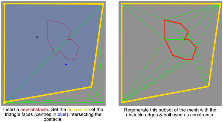
My idea was to find the triangles in the existing mesh that intersect with an obstacle to be inserted, and then generate a delaunay triangulation for this subset of triangles with the addition of the new obstacle. Next, the outline of the subset would be carved out of the base mesh & the updated subset merged into the base mesh.
Append the regenerated mesh subsection to the original mesh, minus the cut-out of the old subset. Merge duplicate vertices and edges.
Removing obstacles
To remove an obstacle I would find all the triangles with centre points that intersected the obstacle, create a set of all the vertices in these triangles, and then additionally get all triangles that use any of these vertices. This extended triangle set defined the subset of the mesh that would need to be regenerated when the obstacle was removed.
Regenerate the hull outline without the obstacle constraints, then replace the subset back into the original mesh.
Edge cases & additional complexities
The basic ideas described above worked quite well but there were additional complexities I encountered, such as ensuring that other obstacles that overlapped the extended triangle set continued to have their edge constraints respected in the new mesh generation.
After getting obstacle insertion on a subset of the navmesh working, I was slightly disheartened to see a less than ideal triangulation that included long & very thin strips. Thankfully I realised this was only because the delaunay triangulation hadn’t been run across the mesh as a whole. Running the edge flipping algorithm across the entire mesh isn’t too expensive if ~98% of the edges are already in the correct state so after obstacle insertion/removal I would run the delaunay algorithm across the entire mesh once more to help keep the mesh triangulation in a better state.
After getting dynamic delaunay working I expanded the testing include a dynamic spinning obstacle rect. To simulate a dynamic obstacle I would insert the obstacle at a different transformation each frame (and destroy the previous frames version of the obstacle), eg. frame1: {add rect1}, frame2: {add rect2, remove rect1}. The rect would be rotated slightly each iteration and positioned at the latest cursor location, but otherwise the same size. This turned out to be a good basic test as it showed up lots of edge cases and bugs.
Only the blue region around the newly inserted obstacle is regenerated
Dynamic updating of the navmesh is a challenging engineering task. There were a lot of edge-cases, many math precision issues and compromises to overcome. It required a lot of careful step by step debugging using verbose visualisation to stay on top of what was happening. This in turn made it one of the most rewarding projects to work on once it was finally working in a robust manner.
Marking Obstacles
Having got a pretty robust fixed-point dynamic navmesh working I was happy to move onto the easier task; using the data in a practical way for pathfinding. To begin with, I needed to flag triangles that were underneath obstacles. This is done with a simple intersection test between the triangle centre & an obstacle polygon in updated subsets of the navmesh.
Obstacles in red
Triangle Spatial Partition
Before a path can be found we need to know which triangles the start and end positions of the path are in. There could be thousands of triangles across the map, and we don’t want to do an intersection test for everyone of them, so a cell based spatial partition map is used to keep this reasonably cheap to query. Each corner of a triangles AABB bounds are added to a multi-map. For large triangles, where the corners don’t include all the grid cells that the triangle area covers, the bounds of the triangle are iterated over by the grid cell width. I imagine there are better spatial partitioning solutions than this for triangles, but it was still an order of magnitude performance increase, easy to write-up and can always be looked into later if required.
The start & end positions are displayed by two red crosses. The dashed squares are the grid cells in the spatial partition that the search positions hash into. The start position need only check against 2 triangles (in white), where as the goal position checks ~20 triangles (in yellow).
Triangle A* Search
With the start and end triangles found, the triangle navmesh data could now be leveraged to get neighbours and write a basic heuristic for an A* algorithm (I used triangle centre distance for now). The A* search & triangle spatial partition were blessedely easy & quick to code up compared to the dynamic constrained delaunay code. The result of this stage gave me a nice path of triangles from the start position to the goal.
The starting position/triangle in white, the goal in yellow & the path of portal edges in blue.
Simple Stupid Funnel Algorithm
The above image shows a path of 14 nodes (triangles) to navigate around two obstacles across a direct 55m distance. This is a decent gain compared to a grid which would require possibly ~55 nodes or more (and that is just the path, not to mention the exponential increase in size of the A* open list), assuming each cell is 1 square metre. Also, as previously mentioned, the other benefit with triangles is that they allow for far more precision relative to the obstacle outlines, compared to a grid.
However, you can’t path based on triangles alone. A path of positions is required for units to be able to follow. This is where the simple stupid funnel algorithm, a type of ‘string pulling’ algorithm, comes in. A list of portal edges is collected by finding the shared edge between each adjacent triangle in the list and then SSF algorithm is used to find the corners in the path.
Edge portals in purple. Direct path in black.
Variable agent size
One of the nice properties of using constrained triangle edges for the portals is that the maximum agent size that can pass through is known by the length of the edge portal. I added an extra parameter to the A* search so that it would ignore edges with shorter lengths than the agent diameter.
The edges on path were now always long enough for an agent to pass through, however, the path positions can’t be right on the boundary of an obstacle, this would only work for zero size agents. To fix this I narrowed the portal edges by the radius of the agent on both ends so that the path corners were adjusted to be away from obstacles.
Agent radius 1. Small agents can hug closely around obstacles for a more efficient path.Agent radius 4. The portal edges have narrowed so that the corners are further from the obstacles. This leads to a different & wider path near the rocks.Agent radius 12. The larger agent has to take an even longer route around the crystals to reach its destination.
It should be noted I’m not sure this will work perfectly on all corners of the navmesh. I can already see a corner when the agent has a radius of 4 where it’s not quite far enough away from an obstacle between path nodes. My hope is that by allowing a little extra buffer on the radius size that this isn’t really an issue in practice.
MapLocation & RayCast
It’s often very useful to be able to get the nearest location available on a navmesh One use-case I had for this was when moving a group of units to a destination, their individual goal positions may vary slightly to within a ‘soft’ / group radius of the final path waypoint – I need to make sure these spread positions aren’t inside an obstacle. The MapLocation function does this by looking up triangles intersecting a circle of specified radius around the target position. It uses the spatial grid to test against only nearby circles. If the target position is inside an obstacle it will map to the nearest valid (not intersecting an obstacle) navmesh location.
Navmesh raycast can be useful for a few things too, including LOS (line of sight) queries. Agents periodically do LOS checks with waypoints further along the path to see if they can skip positions. In addition if an agent has LOS with a destination from the start then a path query may be avoided altogether.
MapLocation: The input position maps to the nearest valid navmesh location. The outer circle denotes the area within which triangle intersection tests are done.
Soft & hard waypoint radius
For groups of agents moving together along the same path it was useful to introduce the concept of a ‘soft’ radius. The soft radius is the maximum radius around a waypoint that may be compressed down to a hard radius depending on obstacles around a waypoint. The hard radius is the minimum radius that must exist along a waypoint on a path request. The hard radius limits the edges that can be traversed in a path request and is set to the largest units radius. The soft radius is set depending on the group size and can be useful to stop a large number of smaller units all competing for the exact same waypoint position.
The soft radius expands so groups of units don’t all compete for a single waypoint position. The hard radius defines the minimum space required on the path.
The soft radius extents are set based on the portal edge length. This method is working fairly well for now. Previously I was setting the soft radius extents after the SSFD string pulling and raycasting either way into navmesh obstacles to determine the extents, however, I found this to be far more error prone, particularly in a maze like structure, compared to using the path portal edges.
Closing Notes
There’s quite a bit of work in the form of maths & problem solving that goes into making a custom navmesh. However, it’s very useful (and probably necessary for some types of games) to be able to have full control of the inner workings when compared to a black-box solution. There is still probably lots of low hanging optimisation that could be done but even in the Unity editor with non-bursted C#, the navmesh updates ~50-100* than Unitys built-in solution for a single obstacle insertion. It’s worth saying again that this doesn’t mean the constrained delaunay navmesh is better in all situations, just that it’s a more well-suited tool for this particular task.
Agents in an RTS often need to pathfind across a map containing various obstacles. Finding the most efficient route at this high-level can be solved with methods such as navigation meshes/grids or flowfields. However, in a fast moving environment with lots of dynamic obstacles moving around & quickly going in & out of existence, it is not always practical to keep making new pathing requests. This is where local navigation techniques, such as boids, can start to be useful.
Iteration with boids demonstrating the behaviours discussed in more detail below
It’s easy to search for a basic introduction to boids, and so, I won’t be discussing that here. Having implemented some basic boids to allow for reasonable group movement there were a few areas I wanted to adjust. This post is a list of notes on the way to improving local avoidance (including agents navigating concave depressions) & implementing a surround mechanic, where a small swarm of melee attackers surround a group of targets.
Spatial Partitioning
Tiles coloured according to agent count
Boids involves lots of comparisons to neighbour agents so having a grid-based spatial partitioning system for dynamic agents helped keep things performant. Systems such as target scanning & boids would access this map to know which agents are nearby, avoiding the otherwise costly O(n2) agent comparisons.
Avoidance
I had originally implemented a separation behaviour but soon realised that a more traditional avoidance force would work better for my goals. There is a behaviour state where the agent is expected to hold it’s position, which is used if the agent is explicitly commanded to do so or if it’s performing some task where it shouldn’t move for other agents, such as attacking. Currently agents could be pushed around by other agents at anytime so a robust avoidance force seemed the best way to fix this.
Initially I used a typical boid separation force which caused the agent to move away from neighbours. This raised the first problem: units getting trapped when surrounded by multiple neighbours. Sometimes they would slow down and eventually push through, other times they would just get stuck as the separation force more or less cancelled out the seek force.
Problem 1: Avoidance force is approximately opposite to seek
I replaced the separation force with a typical boids avoidance force which adjusted the steering to aim either side of a neighbour. The next problem was that the agent avoidance direction was not consistent. It would flicker between two neighbours either side of the agents forward vector.
Problem 2: Non-consistent avoidance direction
To fix the rapid switching of avoidance direction for different neighbours I locked the avoidance force to the same side of the agents forward vector if there was an existing avoidance force (diagrams 1 & 2). This stopped the flickering.
The agent would now navigate around a concave depression of neighbours, however, it had a tendency to continue along the perimeter on the other side of the neighbours rather than head straight for the goal once the path was clear. The solution was to alter the avoidance force to be perpendicular to the goal vector in certain situations (diagrams 3 & 4).
This iteration of the avoidance forces is demonstrated in the video link at the top of this post. It’s worth bearing in mind that in addition to these new ways of calculating the avoidance force, there was a decent amount of iteration tweaking the strength and radius of various boid forces to help get the right effect.
Surrounding
In many RTS games a group of agents can surround an enemy and trap them. This was a very satisfying move to pull off in Warcraft3 in particular where you could trap a high priority hero unit. I wanted something similar to be possible in this prototype. And, in addition to targeting a single agent, I wanted a swarm of melee attackers to spread and surround a defensive block of units. The avoidance work I’d done so far, mentioned above, went a long way to helping achieve the surrounding part, but there were problems. The first problem was targets simply pushing enemy units out of the way to escape. To fix this I had to come up with new rules on who could push who. The seek force of an agent is reduced depending on how much it points towards a close neighbour & what the properties of that neighbour are. ie an enemy would have a strong seek reduction on the moving unit, a friendly holding ground less so. The progression with this behaviour is demonstrated in the linked video too.
Visualisation & Debugging
As can be seen in the video and screenshots, verbose debug visualisation & rapid & easy live tweaking of boid variables is almost essential to getting these behaviours working. Boid activation radii, force arrows sized to magnitude and clear colour coding all went a long way to getting it working as desired. In addition, a replay system or simply recording interactions using a screen recorder program can help considerably. There were lots of times I would rewatch a recording, single stepping through the frames until I understood exactly what was happening and how I might adjust settings or add new behaviours to improve things.
Syncronised Arrival
Sometimes when a group of boids move in a closely packed group I observed that units arriving later would push other arrived units forwards out of position. This wasn’t really desired, so when a unit arrives at a destination it checks if it’s neighbours are in contact with it and zeros their velocity and sets them as arrived too. This appears to make all units in a packed group come to a complete stop over a far smaller number of frames. Previously there was a visible wave-like pattern visible of the units stopping that spread over multiple frames.
Syncronised stop is disabled if a unit isn’t within a threshold distance to the movement goal, this means that units too far away will push others forwards until they enter within this larger stopping distance. I added this so that units stop in a smaller circular radius around the movement goal, rather than a long thin line of units forming (like a line of ants coming to a stop).
Since Unity’s data-orientated tech stack (DOTS) appeared there have been quite a few tech demos testing it out. Writing flowfield implementations seems to have recently become popular in the niche crowd of early adopter Unity game tech enthusiasts. Flowfields were first used in games such as Supreme Command 2 and then later Planetary Annihilation. They make sense when you have very large numbers of agents path-finding. The initial cost for a single agent is going to be higher than using something like a NavMesh but as you get into the hundreds or thousands of agents they may scale better.
For an RTS pathfinding prototype I initially used Unity’s built in NavMesh with the hybrid-DOTs navmesh query API. It was very fast for path queries but struggled performance wise when updating the NavMesh with dynamic obstacles. When weighing up the pros/cons of various methods I thought flowfields could be well suited since my problem-case involves large numbers of units. The grid data-structure inherent with flowfields can also be useful for storing other map information such as additional movement costs, heights, island IDs (an island is a single isolated area of the the grid that can’t path to another island). The grid data structure is also quite quick to look-up information in. Finally, for an RTS style project, pathfinding is one of the most critical bits of tech and having full control & understanding over it with no blackboxes was desirable (which wasn’t the case with using Unitys out-of-the-box implementation) and I had some ambitious highly specific goals that I wasn’t sure would be accommodated by Unitys built-in solution.
Making a basic dijkstra flowfield is one thing but a robust RTS game can be a lot more involved, and may require a fair few additional items such as:
Flowfield tiles
Hierarchical A* or some other high level pathing between tile portals
Caching of paths & flowfield tiles
Eikonal solver for smoother cost field generation
Greater than 8 directions for each cell for smoother movement
Line of sight (LOS) flags for smoother movement
Parallelised generation of paths and flowfields
There’s lots of media on the internet of people doing a basic implementation but it’s hard to find many that are using it in more complex situations such as an RTS game. The basics of flowfields are already well explained in numerous blogs and youtube videos such as this great one at HowToRTS https://howtorts.github.io/2014/01/04/basic-flow-fields.html. Although I might touch on some basics below, in general the rest of this post will assume a knowledge of basic flowfields. The following is more a collection of notes & workings I collected recently whilst trying to implement flowfields in a prototype RTS, rather than a robust tutorial.
Dijkstra vs Eikonal cost spread
The Dijkstra flood filling algorithm is used to expand the cells of the flowfield. Given a starting cell, the path goal, it will spread to all valid neighbour cells.
Flowfield spread visualised with different iteration counts. Cost increases as colour changes outwards from centre.
Whilst running the Dijkstra algorithm you can calculate cost in a basic way by simply incrementally increasing as it spreads (like image 2 below), however, this can lead to diamond like patterns forming in the cost field. This may in turn lead to slightly geometric looking path movement.
Image 2. Dijkstra cost field with a very low cost colour wavelength, basically the colour changes more frequently as the cost changes. This can help to see cost-spread patterns better.
Smoother cost spread can be generated by using using an Eikonal solver as shown in image 3. This can lead to more optimal paths, especially if there are up to 16 possible directions per a cell available.
Image 3. Eikonal equation generating a smoother more spherical cost field.
To create flowfields across the entire map area would be very costly so an initial optimisation is to only generate the flowfield across a high-level (or hierarchical) path. To accomplish this the map is divided up into tiles. Flowfields will be generated for the tiles that are on the hierarchical path. After some basic optimisation a single 50*50 flowfield area generates in ~0.3ms. The map itself is ten times this size. The map is represented by a 500*500 grid, which is divided into 100 50*50 tiles.
The underlying map grid. Green cells are passable, red cells are obstacles.
When a path is required, hierarchical A* is run through tile portals (explained more below). The result of this is a list of tiles that the path runs through. Flowfields are requested for these tiles and the units read the direction value on their cell to get to the destination.
A map tile with portal cells in pink and paths in green between the portals. The length of these paths is the cost of the edge in the hierarchical A* graph.Green lines visualising the hierarchical graph edges
Other tips
Debug visualisation is very important obviously with this sort of work. It’s really worth putting some time in here to have a robust visualisation system to keep you sane & discover bugs quickly.
Using a branchless math.select in GetNeighbours to replace if branches gave a crazy 10* speed-up compared to the if else branching I was doing previously. Although this will vary on the compiler it’s probably worth giving some serious consideration to, profiling before & after.
eg. here is a snippet of the branching version of some code to find neighbour indices on a grid:
if (x > 0)
{
	int neighbourIndex = ((x - 1) + (gridWidth * z));
	neighbours [neighboursCount ++] = neighbourIndex;

	if (z > 0)
	{
		neighbourIndex = ((x - 1) + (z - 1) * gridWidth);
		neighbours [neighboursCount ++] = neighbourIndex;
	}

	if (z < (gridHeight - 1))
	{
		neighbourIndex = ((x - 1) + (z + 1) * gridWidth);
		neighbours [neighboursCount ++] = neighbourIndex;
	}
}
Making sure to access large grid/tile based arrays in a cache aware way was very important. eg. if you are iterating over large arrays (such as flowfield tile data) make sure you are going in the right column/row major direction to avoid jumping about in memory, or just use 1 rather than 2 dimension loop statements. This was another thing I got wrong first but fixed after profiling and checking the code.
Writing the flowfield implementation started with the need to have more control over the pathfinding implementation but it ended up being a decent revision for writing faster data-orientated code.
Closing Notes – movement behaviours
Having got reasonably well optimised and usable flowfields working I soon found out I was still someway from having large group movement work without any issues. A single unit could get to its destination fine. A small group was ok. But when 100 or so units all had to move around a corner to a common destination they tended to cluster quickly and end up forming into a single/double file line, like a line of ants. This was not what I had in mind. My original goal was to achieve something like Starcraft2 which has with a very smooth & responsive level of control for group movement. Specifically, when going around a corner, I wanted the group to move around a centralised centre as one, more or less maintaining relative offsets to each other. A lot of this would be dramatically helped by adding some boids style localised forces. However, even after some initial work in that area I couldn’t quite get it to fix the problem entirely with large groups of units when using flowfields.
Formations forces applied in addition to the flowfield are a potential idea to solve this problem, but I’ve not been able to get this to work yet in practice. The group movement just didn’t look well suited to the situation. Although it could be more appropriate when trying to model an actual swarm of insects or liquid like things. I might revisit flowfields for swarm style units or multiple goal based paths (such as close combat fighting with groups) in the future.
I shelved the flowfield work whilst keeping it as an option to switch back to if required and started on a new approach. I went back to using a more traditional pathing solution involving waypoints at path corners which you can then apply offsets to and assign individual positions per unit. This method would also need a lot of boid forces interplay but the path destinations would hopefully be more precise at least.
Resisting the urge to go back to Unity NavMesh and its slow rebuild/update times, I started using my existing ‘NavGrid’ with plain old grid based A* searches. Although the path search cost for a grid is higher than I’d expect from a good NavMesh implementation the insertion or rebuild time for a grid based graph is trivial, and I had ambitious ideas that involved regular updates of the graph. I tweaked the heuristics and added a tie-breaker http://theory.stanford.edu/~amitp/GameProgramming/Heuristics.html to improve the efficiency. Then I calculated the path ‘corners’ or waypoints along the path.
The path corner positions could then be used to calculate position offsets of varying length depending on the group size allowing for better formation movement.
I wanted to do some prototyping with time-manipulating mechanics in a casual RTS project. I always found the gameplay and technical implementation details of games that have experimented in this area (such as Braid and Achron) very interesting. To begin with I’m curious to see what it would be like to allow players to see the future and also have the ability to rewind back to the past. I thought it would be fun to figure out the technical implementation and was curious if it would make for interesting gameplay too.
Past and Future
Rewinding to past states can be accomplished with recording game state. This could be similar to the method described in Braid, though I’m not sure yet if I’d want all the frames up to the rewind time or just a single snapshot of the world at the target time in the past.
To know the ‘current future’ (the future assuming no new player inputs) I plan to run a second version of the game simulation ahead of the present. For the future to be true the simulation must be deterministic. I’ve made a deterministic RTS in the past using fixed-point maths but Unity’s new DOTs (data-orientated-technology-stack) comes with a Burst compiler that is planning to support cross-platform deterministic floating point maths eventually. In addition it has multi-threading job and entity component systems that have got a lot better over the last two years. It seemed like a good fit to start using these to write my simulation code in. I did also dabble in writing a native plugin in C++ but in the end it became apparent I was going to spend a great deal of time recreating things that Unity can adequately do. The burst compiler doesn’t give cross-platform determinism yet but Unity ECS, and DOTS Physics are deterministic on the same CPU architectures. This is enough to start prototyping with for now.
Simulation & Presentation
I setup a basic casual ClashRoyale style RTS with debug rendering. The game battle code is split between the simulation, which is the battle logic, and the presentation, which is the rendering of the simulation state. The simulation can be stepped multiple times independently of a presentation update. This is useful when running multiple worlds (such as a predicted future world in this case) where you may not want to render after every update. It’s also a great debug feature. To display the future I plan to run a second simulation world 7 seconds ahead of the present time. The first task is to ensure that the simulation is deterministic so that the future is true.
A reasonably busy test battle scenario was setup and run multiple times to start testing determinism. It was quickly obvious that the sim wasn’t deterministic at all, with units in different positions & health states across multiple runs. To address this, checksum hash calculations were added for key data such as unit positions, health and locomotive forces in order to diagnose where determinism was lost.
The checksum calculations are logged to a file at the end of the sim update. Each checksum entry has the value and a description which is usually the file and line number. After a few checksum calculations were added the determinism break was found to come from some multi-threaded jobs in the locomotion & health system. Realising that Unity’s NativeMultiHashmap.Concurrent is not deterministic; I removed the use of ScheduleParallel calls involving this container (it wasn’t especially necessary anyway). This lead to identical checksum values on every run. Having the ability to step the sim up to and over 1000 updates in approximately one second (this skips rendering and updates the sim in a loop from a single FixedUpdate call), really helped increase iteration time.
Being able to step 1000 updates in the sim instantly can speed up debugging
Implementation Details
To have this level of control of the simulation and presentation systems, ICustomBootstrap was used to override Unitys ECS world creation. All the standard Unity systems are created but not added to the automatic player update loop. Game systems are not added to any of the Unity system groups or the player loop; I manually update the game systems inline as shown below.
int logicFramesToProcess = m_paused ? m_singleStepCount : 1;

if (logicFramesToProcess > 0)
{
   for (int step = 0; step < logicFramesToProcess; ++step)
   {
    StepSimLogic ();

    int simStepsProcessed = m_simStepCount - 1;
    Checksum.FlushToFile (simStepsProcessed);
  }

  StepViewLogic ();
}
For now I’ve preferred to update most of my own systems manually inline rather than using Unitys [UpdateBefore(systemA),UpdateAfter (systemB)] attributes. However, it is important to note that there is a CollisionEvents system that must be updated after StepPhysicsWorld and before EndFramePhysicsSystem. CollisionEvents is therefore added to the standard SimulationSystemGroup so its update is coordinated correctly with the Unity.Physics systems.
ICustomBootstrap is overridden to store sim, view or unity systems in lists and create all worlds required. Note there is no call for ScriptBehaviourUpdateOrder.UpdatePlayerLoop(world); because I want to manually control system update order and timing.
public bool Initialize (string defaultWorldName)
{
  Debug.Assert (s_instance == null);
  s_instance = this;

  Debug.Log ("BattleManager.ICustomBootstrap.Initialize");

  IReadOnlyList<Type> systems = DefaultWorldInitialization.GetAllSystems (WorldSystemFilterFlags.Default);
  List<Type> simGameSystems = new List<Type> ();
  List<Type> viewGameSystems = new List<Type> ();
  List<Type> unitySystems = new List<Type> ();

  for (int i = 0; i < systems.Count; i ++)
  {
    if (systems [i].Namespace == "Sim")
    {
      simGameSystems.Add (systems [i]);
      continue;
    }
    else if (systems [i].Namespace == "View")
    {
      viewGameSystems.Add (systems [i]);
      continue;
    }

    unitySystems.Add (systems [i]);
  }

  //
  // Make an exception for ExportPhysicsEventsSystem as it must be updated
  // between various Unity.Physics.Systems

  simGameSystems.Remove (typeof (Sim.ExportPhysicsEventsSystem));
  unitySystems.Add (typeof (Sim.ExportPhysicsEventsSystem));

  //
  // Initialise worlds

  m_presentWorld = new WorldController ();
  m_presentWorld.Initialise ("sim", simGameSystems, viewGameSystems, unitySystems);

  World.DefaultGameObjectInjectionWorld = m_presentWorld.m_simWorld;

  m_alternateWorld = new WorldController ();
  m_alternateWorld.Initialise ("past", simGameSystems, viewGameSystems, unitySystems);

  const bool defaultWorldInitialisationDone = true;
  return defaultWorldInitialisationDone;
}
Later in the initialisation flow a single update of m_presentWorld is done before its data is copied. m_presentWorld was set to the DefaultGameObjectInjectionWorld so it contains all the converted GameObject data. Copying the data over gives both worlds the exact same starting state.
//
// Update present world once for game object conversion systems and then
// copy all entities into the alternate world.

m_presentWorld.m_simWorld.Update ();
MemoryBinaryWriter memoryWriter = new MemoryBinaryWriter ();
SerializeUtility.SerializeWorld (m_presentWorld.m_simEntityManager, memoryWriter, out object [] unityObjects);

unsafe
{
  MemoryBinaryReader memoryReader = new MemoryBinaryReader (memoryWriter.Data);
  ExclusiveEntityTransaction transaction = m_alternateWorld.m_simEntityManager.BeginExclusiveEntityTransaction ();
  SerializeUtility.DeserializeWorld (transaction, memoryReader, unityObjects);
  m_alternateWorld.m_simEntityManager.EndExclusiveEntityTransaction ();
}